
Introduction
NOTE: If you haven’t read Part 1 of the Underwater ROV Project series, check it out!
FAIR WARNING: This post has a decent amount of pictures.
What a journey! Welcome to part 2 of my ROV project. This was supposed to be a 2-part series, but destiny has determined that more is to come — mainly due to a variety of delays:
- Found out the Ethernet cable I ordered required special (Smaller) RJ45 connectors. Had trouble sourcing them. Had to get them shipped. Shipping was slow.
- Motor controllers (ESCs shipped from China – via Ali Express) were ordered in mid-October 2019 and did not arrive until February 2020 – same with the M2 mounting screws and spacers required to fix the RJ45 chip to the sub’s electronics plate. Both orders had to be cancelled and then re-ordered (with plenty of communication between myself and the suppliers).
- COVID-19 hit the world. Pretty self-explanatory.
- The ribbon that I received with my RaspberryPi camera did not fit the RasperryPi Zero. This meant that I needed to order the ‘adapter’ ribbon to be able to connect the Zero properly. Shipping took months. When the new ribbon arrived it was bent to the point that the data stream was corrupted. Will have to order a new one/talk to the suppliers.
- The electronics plate required a modification to accommodate the motor controllers (a few precision cuts through the 3mm aluminum plate). I did not have the equipment to do this but the person who did was quarantined. Can’t blame them really.
- Decided to take the Penetration with Kali course and get my OSCP while stuck inside due to COVID. This course is great, but it takes WAY more time than you ever expect. The moment this course started, all ROV work stopped. I am about 100 days into the 150 days I bought. I’ll write about my experience in a future post.
Suffice it to say a large portion of this ‘leg’ of the project was spent waiting for shipping and modifications. I spent the time writing the control software for the sub, waiting for parts to be shipped, and starting another project that, I’m sure, will eventually make its way onto this site.
Let’s take a look at the progress so far…
ROV Progress
A general note: As with many of these types of projects, it starts out heavy on the “chassis” and mechanical bits to make a platform, then the focus shifts more to the electronics side, then shifts again to the software side. You can’t write software if you don’t have an electronics stack in place and you need to know a bit about the physical platform before you can design the electronics. The pros do all this in SolidWorks or something similar. I have graph paper and glue — for corrections.
Chassis Work
In Part 1, the chassis (wet and dry) looked like just a tube and some PVC. NOW it looks like a tube and some PVC with sass!
Changes:
- Mounted thrusters to chassis
- Built 2 waterproof LED lights from scratch – only one ended up working – and mounted it to the chassis.
- Drilled some holes in the “dry chassis” (The acrylic tube) to allow the cables to feed through. Sounds simple, but had to make sure the acrylic tubing didn’t crack and needed to make sure that the holes were appropriate – each hole will introduce a potential failure point.
- Ordered proper bulkhead waterproof cable grommets for the wet-to-dry cables. Arrived. Need to drill slightly larger holes in bulkhead to accommodate them – though this should reduce potential for leaks.
Mounting thrusters would seem like a simple idea — just bolt them on, right?? but center of gravity and center of force need to be taken into account. Axis of movements need to be considered: Do I want the sub to easily slide laterally or tilt upwards and downwards? Where are the obvious points on the chassis to mount thrusters? What about cable management? All of a sudden you start to get concerned… did I do this right? The answer is probably “no”, but I’m going for “It works! Sweet!”, not perfection. My motto going into this has been: “If it doesn’t blow up when it hits the water then it is a win”… that’s saying a lot when you’re dealing with a Li-Po battery pack. Thrusters were mounted with metal strapping.
Fun fact: complementing thrusters are mounted with clockwise and counter-clockwise configurations. Make sure you remember that.
The lights (correction: light — singular) caused me heartburn. They aren’t perfect, but they work well. I ended up buying a cheap LED flashlight and modifying it, then adding a waterproof connector — then mounted it to the chassis with the same techniques as the thrusters.
Drilling holes in a container that is meant to keep water out seems counter-intuitive, but the power cables need to get in somehow. I practiced on some scrap acrylic tubing first. I had to keep a high drill speed and regulate pressure to keep it from cracking — bad side to doing this is that the drill bit heats up and starts melting the acrylic. Had to file down the edges. Will use grommets to seal the cables with a water-tight wrapping.

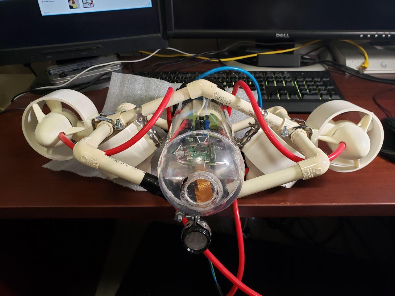
(Above) The ROV, up-side-down — as the light would be crushed. Thrusters and completed light assembly mounted.

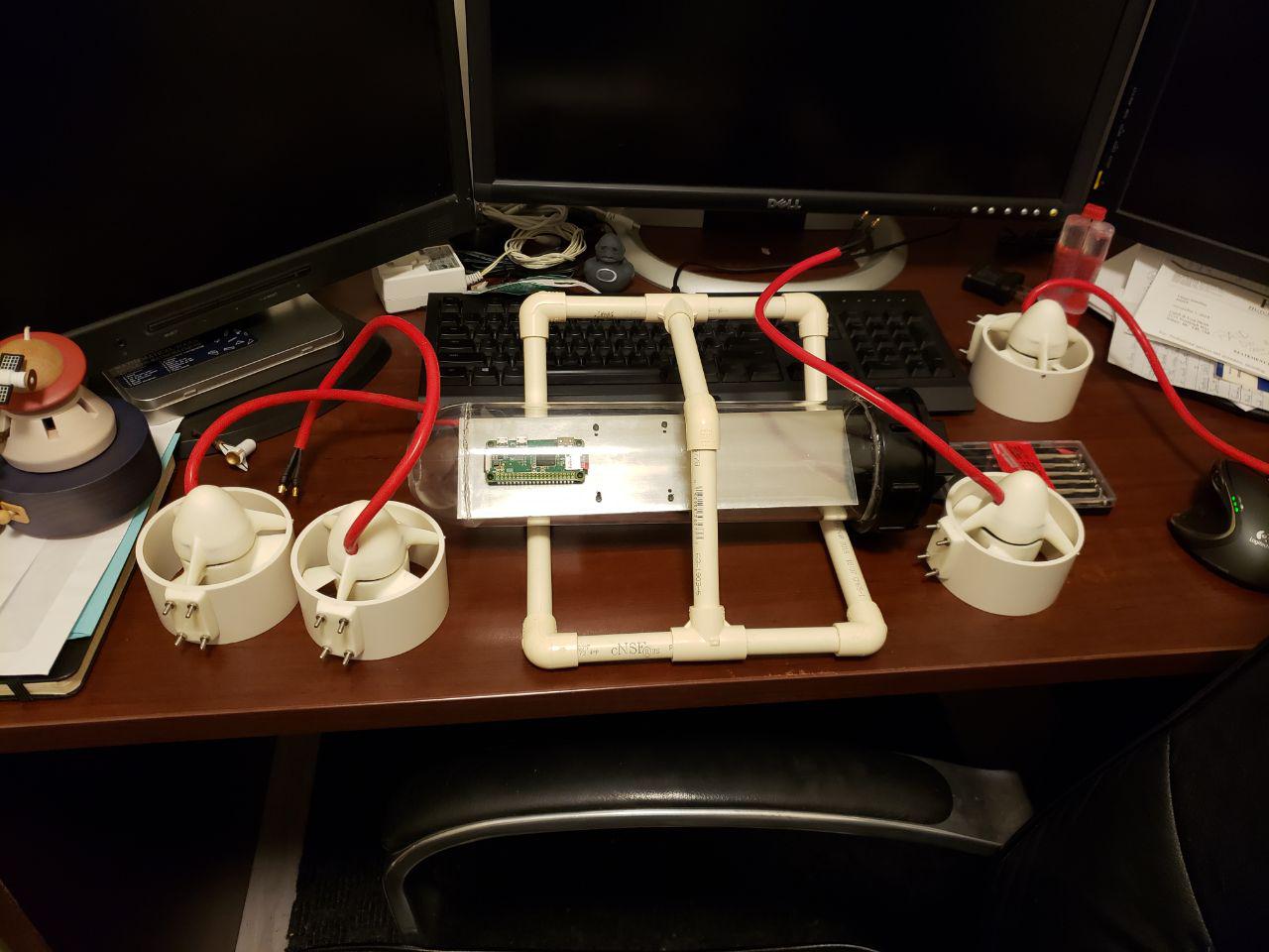
(Above) The ROV before mounting the light assembly. Front-view, right-side-up. Yep, each of those thrusters are capable of 3-5 kg of thrust… if I ever find a way to cram in that much power.

(Above) The cables are starting to pile up.

(Above) RJ45 to RJ45 waterproof adapter — so I don’t have to take the sub apart to disconnect it.
Electronics
Electronics dominated this part of the project and much time was spent soldering.
Changes:
- Ordered and received 100 feet of flat CAT6 Ethernet cable and a waterproof RJ45 connector. The Ethernet cable would be the tether for the sub in addition to sending the joystick’s commands (and sending video to the base station). The cable had to be clipped, the waterproof connector “casing” added, then a new RJ45 connector crimped to the “clipped” end. Turns out that the flat CAT6 Ethernet cables require special RJ45 connectors (they are AWG30 instead of AWG24 – the normal connectors are just not accurate enough to handle the smaller AWG30 wires).
- Ordered and received the voltage regulator to power the sub by battery. Tested and successfully ran the onboard computer (Pi Zero) from battery power with no hitches. Plenty of testing done here to ensure I don’t fry the Zero. Also made a wiring harness that splits the battery power. One stream goes to the voltage regulator (ultimately to the Zero) and the other will go to the ESCs (Motor controllers) to power the thrusters.
- Soldered a 40-pin header to the General Purpose Input/Output (GPIO) connectors. This took a lot of patience and a steady hand. I practiced before the main event. Once soldered, I tested each GPIO connection that I planned to use with a small script and an LED. The script just turned the LED on and off if the connection was good. These pins will be used to control the thrusters (through the ESCs) and lights.
- Ripped apart an RJ45 to Micro-USB adapter and mounted the chip to the electronics board. This allowed me to start connecting to the Raspberry Pi Zero directly and start writing the onboard control software.
- Started soldering the main power cables (and connectors) for the thrusters. Then didn’t like my 2-pin connectors and ordered 3-pin ones. Waited for shipping, they arrived, and haven’t soldered them on yet — though this will clean up the wiring a lot!
- Got the ESCs finally! They’re massive and I had to think about real-estate for the first time. I thought I had enough room but the ESCs are big!
- Ordered and received the camera mount for the camera. BLOCKED: Need to finish testing the camera before I mount it – make sure things are on correctly, resolution, clarity, etc. (See issues/delays list above)
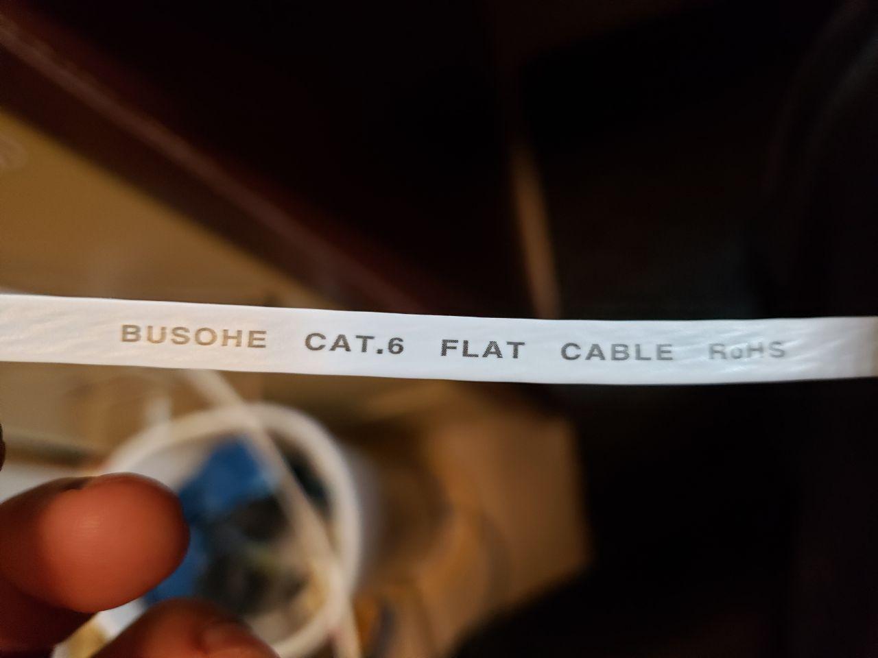
(Above) Flat CAT6 cable that will be my tether.

(Above) Side view of flat CAT6
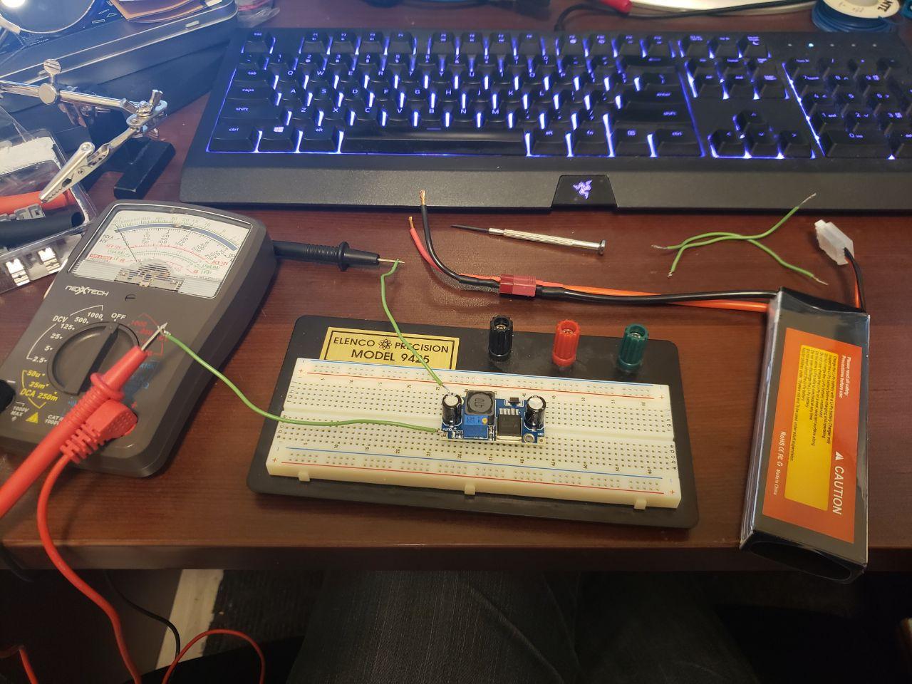
(Above) Testing and configuring variable voltage regulator to ~5V to power the PI Zero.
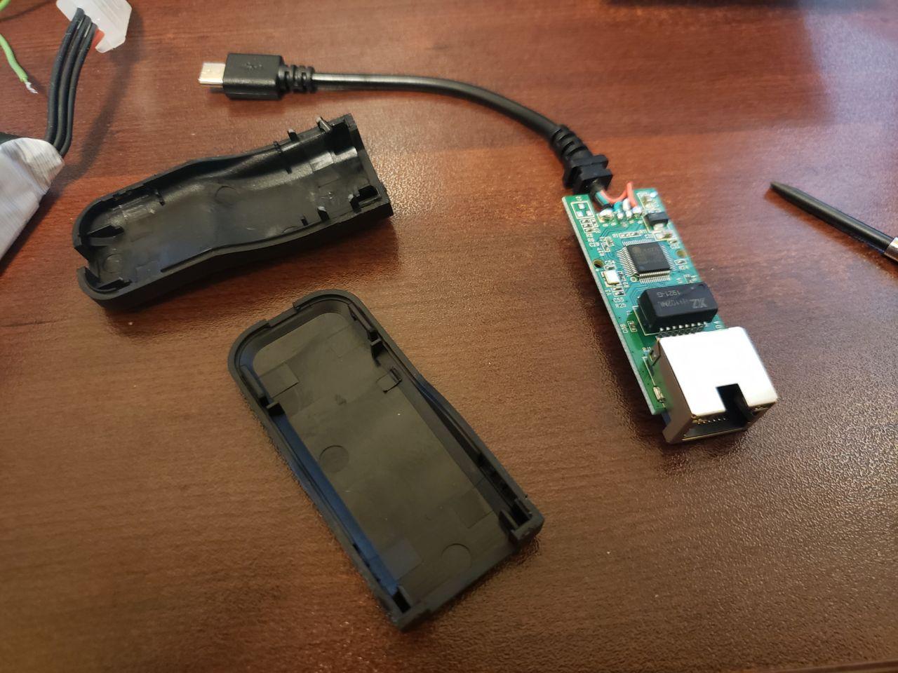
(Above) Stripped Ethernet to micro-USB adapter — for connecting to the PI Zero.
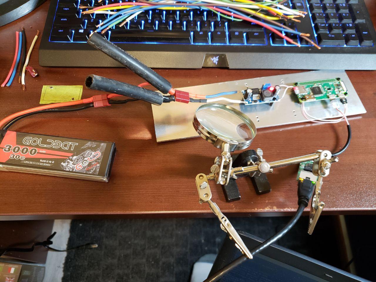
(Above) Running the PI Zero from battery and successfully connecting to it via Ethernet adapter.
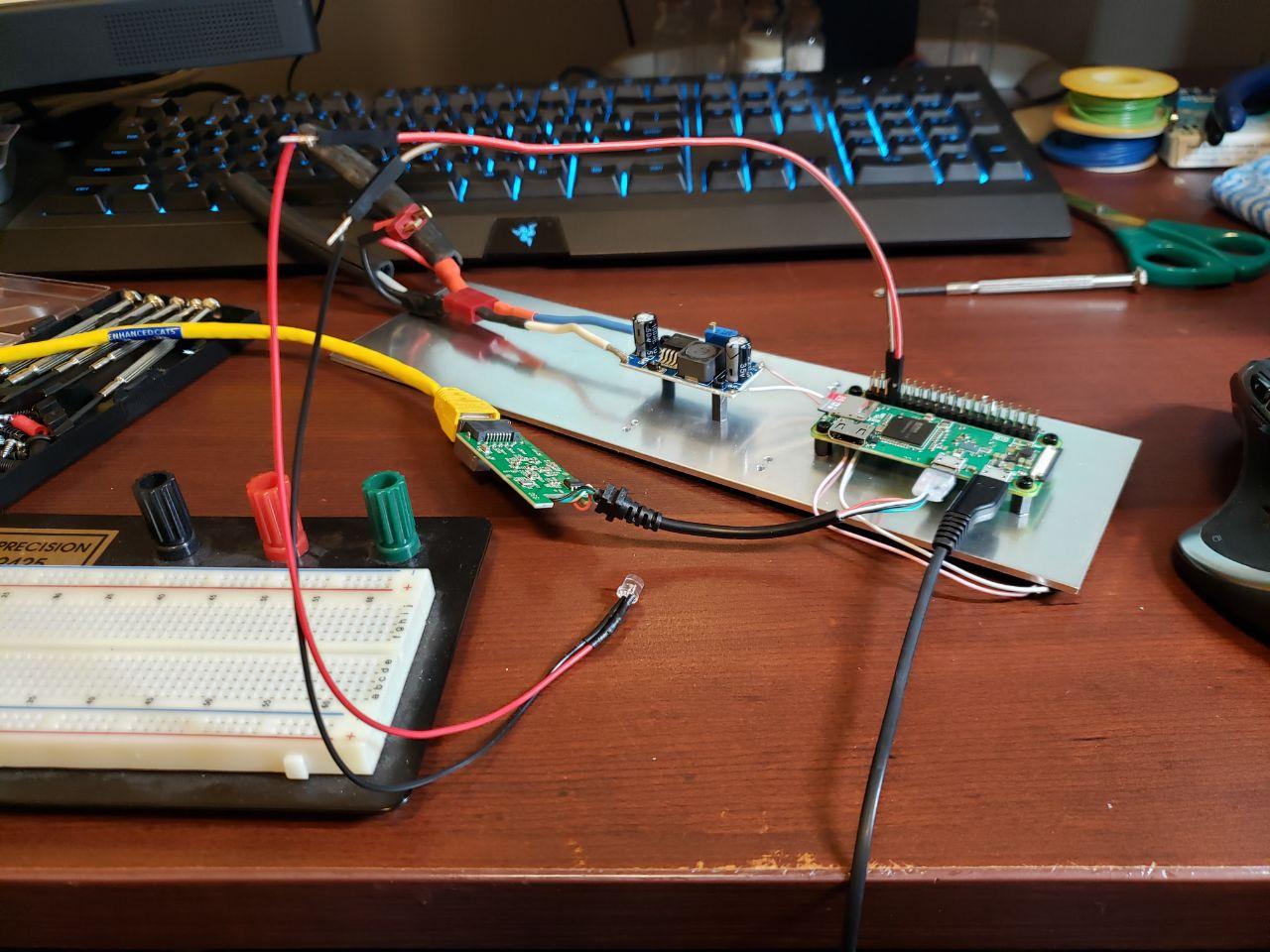
(Above) Soldered GPIO harness and testing each pin using an LED and some test software (via Ethernet)

(Above) Fully mounted PI Zero, voltage regulator, Ethernet adapter, and camera. Also, the 4 motor controllers for the thrusters — taped in banks of 2.
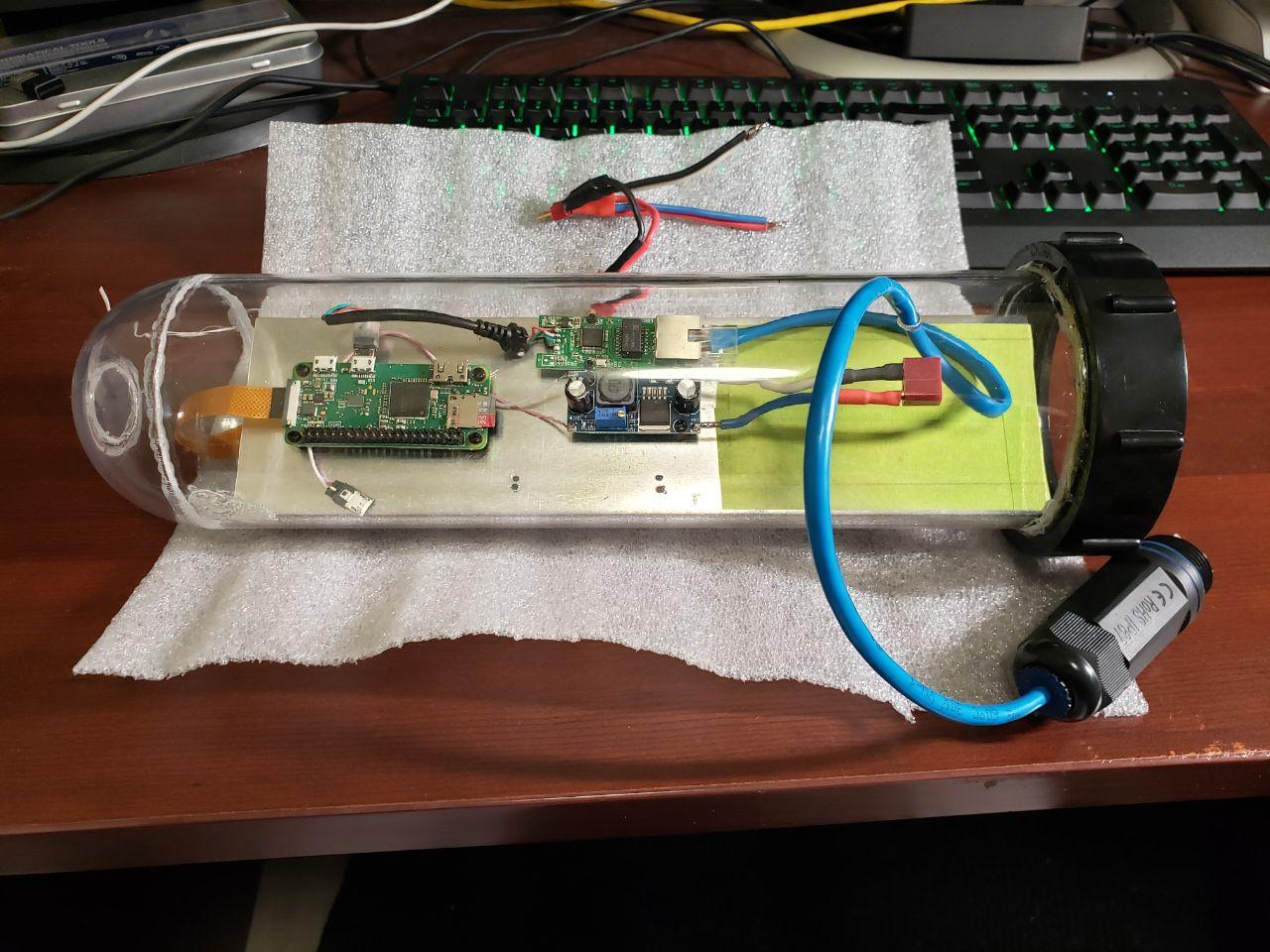
(Above) Electronics stack in the dry chassis — without battery and ESCs (camera unmounted).
Software
NOTE: This will start to become a larger and larger part of the project.
It’s hard to take pictures of software.
Changes:
- Finished writing the control drivers for the ‘shore’ station. Takes basic joystick input and translates it to ROV controls. Then tries to send it to the sub. Have tested the basic video feed (distorted due to issues – see above). Still need to write the ‘on-board’ drivers and software.
Summary
I was hoping to have the sub done by the Summer, but things happen. I’ve made great progress in the past months (before I started the OSCP) and will continue it once I am done the course.
Here is a comparison of the end of Part 1 and the end or Part 2. Hopefully Part 3 continues the progress!
(Above) End of Part 1

(Above) End of Part 2 (Top View)
(Above) End of Part 2 (Front View)

You must be logged in to post a comment.