
Introduction
As as the tides ebb and flow so do my posts.
For the last 6 months I have been designing, sourcing parts for, and building an underwater “Remotely Operated Vehicle” (ROV). It started from a simple thought, “what should I do with my Raspberry Pi zero?” and turned into a multi-month, $400 expenditure that has taught me much about electronics and various kinds of fabrication.
Why an underwater ROV? Well, I live near the Pacific Ocean and spent 2 years writing control software for a competitive Autonomous Underwater Vehicle (AUV) team. Where an ROV needs a human controller (usually through a joystick) an AUV is fully autonomous and has no line going to shore or to a ship. It makes decisions “by itself”.
The ROV I am currently building has AUV capabilities but I have not written the software for it just yet. I plan to in the future.
I plan to chronicle my ROV’s construction and this is the first of a 2-part series on it.
A Quick Design Overview

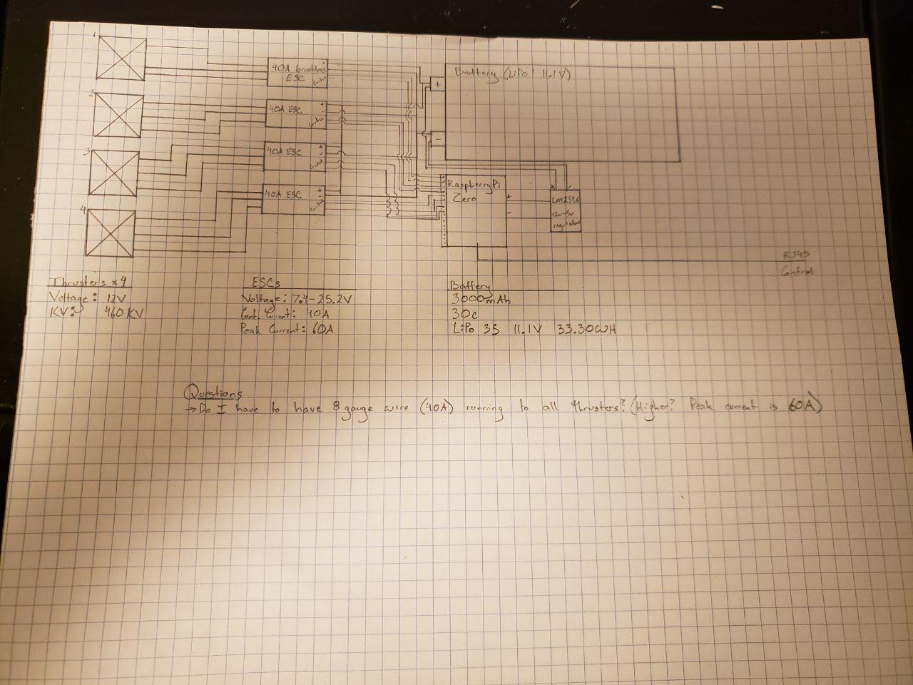
Most of my projects like this start with some graph paper and sketches. The diagram above does not include any thrusters as I did not know what was available at the time but knew the specifications needed. I also was unsure what battery I was going to use so I left the tolerances as guidelines in case I needed something larger than a 3s LiPo battery (my planned power pack).
As you can see from the diagram, there is a central tube that houses the electronics stack, fuses, battery, etc. This is dry and will require a strong seal that is also removable (we will get to that). There is a clear dome at the front for the camera to be placed for vision.
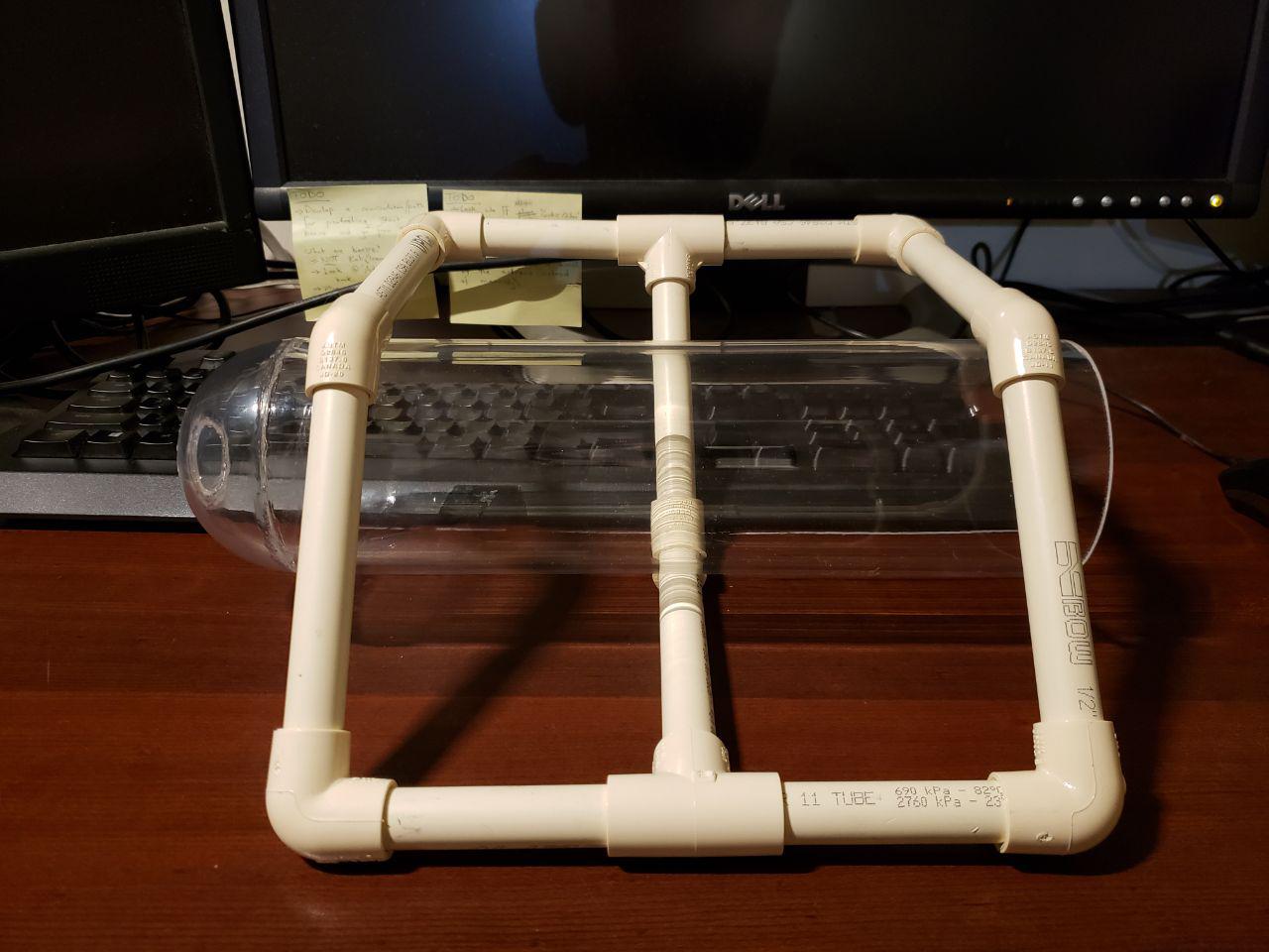
Then there is the scaffolding. This is made from 1/2 inch PVC pipe that will allow for peripherals such as lights and thrusters to be attached.
The Chassis
Materials sourced:
- 1/2 inch PVC pipe (1 6-foot length) and elbows (90 and 45 degree) (sourced from local hardware store)
- 3 inch (inner diameter) clear acrylic tube from local acrylics store (cam in a 6-foot length)
- 3 1/4 inch (outer diameter) acrylic dome for camera at the nose (Sourced and shipped from KitKraft.com)
- Acrylic Cement (I had on hand)
- 2-Part Epoxy (Nothing special, just used this as my second coat for seals — sourced from local hardware store)
I used my Mitre saw with a 100-tooth blade to cut the acrylic tube to the appropriate length. I had to be careful as the heat could score the acrylic but needed to use a finer blade to make sure that I didn’t crack the tube while cutting it. This went very well. 10/10 would recommend. After cutting I used a file to smooth down the edges and prep them for the cement.
The domes took about 2 weeks to get to me and came with a slight bump in the center. This ruined my plan to place the camera in the center as the bump distorted the view. To fix this I ordered 1-inch lenses from Amazon (about a week shipping). I then cut off the front of the dome and cemented the lens to the front.
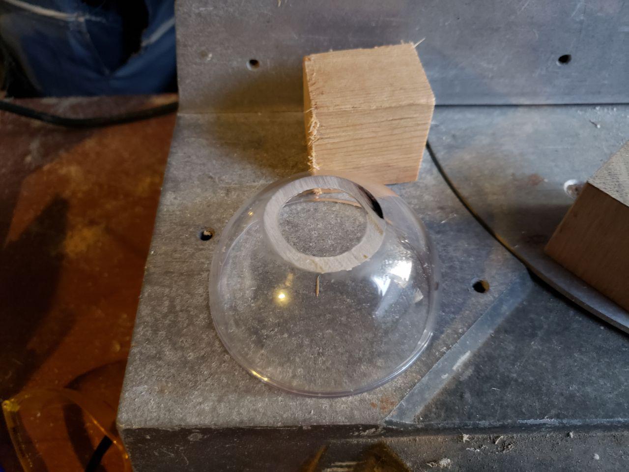
(Above) Cleanly cut acrylic dome.

Not my best work, but it passes the water pressure test and I’m only rating this ROV to about 30 meters under water (about 3 atmospheres of pressure).
Once all the pieces arrived I use the acrylic cement to put it all together. I left the assembly to set for 24 hours.


(Above) The acrylic assembly
After completing the “dry chassis” I assembled the scaffolding by measuring and dry-fitting the pieces. I didn’t cement them in place as there will be some movement later on. After assembly the chassis looks like this:
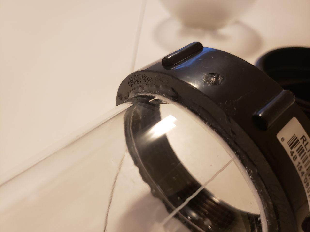
The sealed end caused me a lot of trouble. It’s not like you can just go to a store and ask for an end-cap that plugs into an acrylic tube…. right? I ended up browsing hardware stores for a while to find the right piece. It was a 3 inch sewage end cap (3 In. ABS Male Plug MIPT) and threaded casing — even better, it came with a rubber gasket to complete the water-tight seal. This wasn’t exact and I had to use a hacksaw to cut away the pipe part and leave just the threaded part. Then I had to use some wood-carving tools to carve a proper setting in the pipe for the acrylic portion to sit. This would also help with the cement seal:

(Above) The cut threaded fitting

(Above) Some cheap wood-carving tools that work well for cleaning up the cut and carving a proper setting for the acrylic tube.

(Above) Finished carved setting in the ABS fitting. A quick, light sand helps with the cement too.
(Above) Cemented Acrylic tube to the ABS setting

(Above) The final product — after everything set.
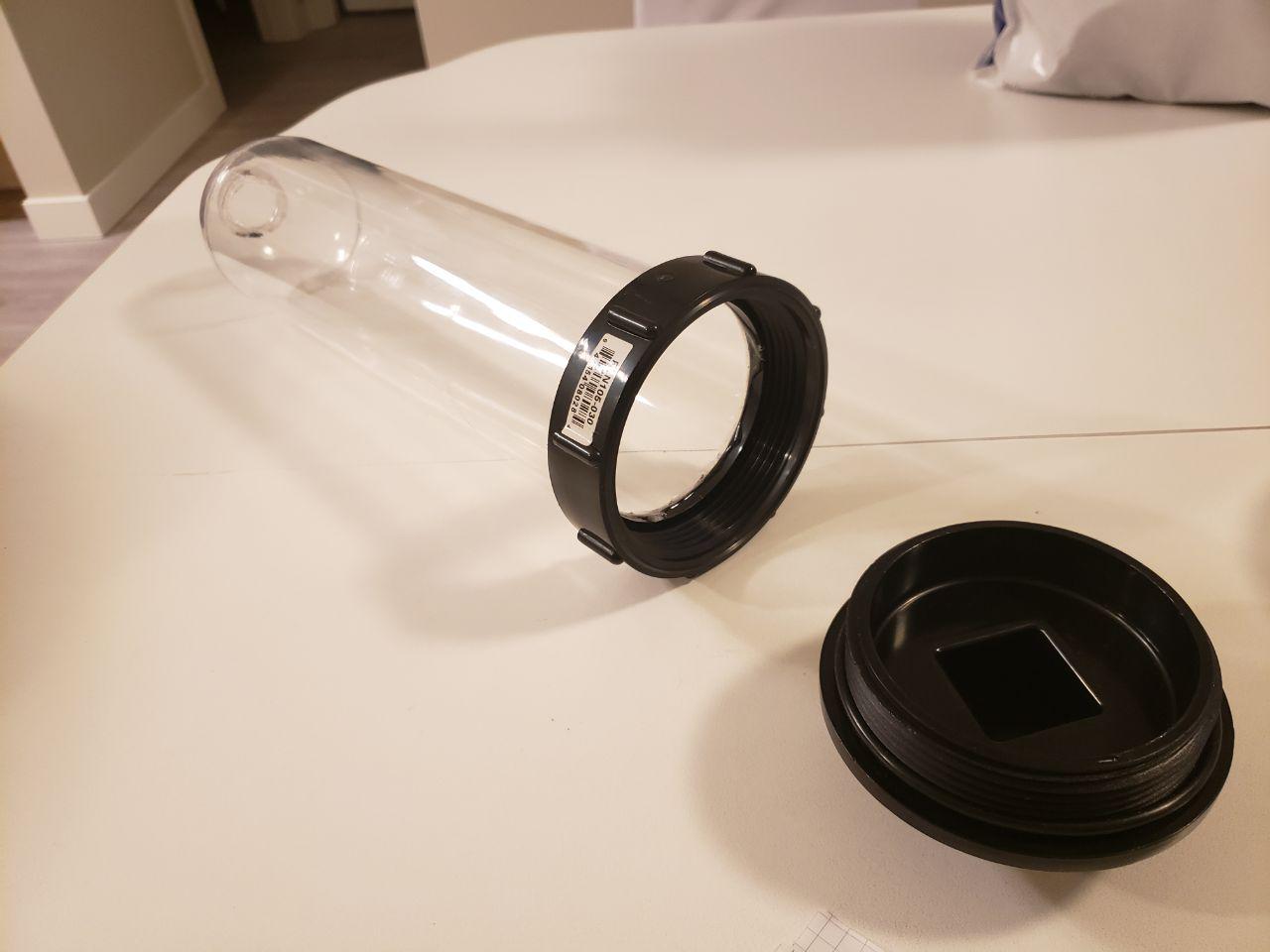
(Above) The 2 fittings and access to the inside of the “dry chassis”.
Electronics
Now that the chassis is starting to take shape, and while I had to wait for shipping of more parts, I started planning my electronics stack.
I knew that I would use the Raspberry Pi Zero as my controller and had to make sure that it could support my planned 4 thrusters. Some research and draft wiring diagrams later proved that it was possible, and I started looking for the appropriate parts:
- 3000 mAh, 11.1V w/ 30C LiPo Battery (From Amazon)
- 12V to 5V voltage regulator (AliExpress) to power the Pi from the battery
- 4x 11.1V Brushless Motor Thrusters (2 CCW and 2 CW) (AliExpress)
- Raspberry Pi Camera V2 – 8MP (https://www.buyapi.ca/)
- 4x 40A Brushless Motor ESCs (AliExpress)
- Raspberry Pi Zero (Already had)
- MicroUSB to ethernet adapter (for later when I want to tether the sub through ethernet — Pi Zero needs it)
Again, a sketch:
What is not in there are a few fuses that I will be placing to make sure that things don’t blow up on me.
The keen ones will notice that the thrusters are massive… and the 3000mAh battery I have would only be able to run for a short period of time before draining. This is true. Each thruster is rated for 3-5kg of thrust. My ROV when complete will weigh approximately 1 kg and will be quite streamlined — so there isn’t really a need to use the thrusters to their full capacity. My plan is to regulate the thrust through the ESCs and limit draw in a variety of ways: Software max thrust limit (write the software to limit the max draw), and use fuses that are lower than the peak draw. Worst-case I blow a fuse — which isn’t ideal but keeps things regulated. My hope is that the software will be enough and the fuses are a fail-safe.
The electronics are mounted on a 3mm thick aluminum plate that I had cut to the specifications of the inner hull (“dry chassis”). This is also light but strong enough to prevent bending and warping. I drilled holes in it and put spacers on it to mount the RaspberryPi Zero and the battery. This makes it so the entire electronics stack can be pulled out of the inner hull and worked on, have batteries changed, etc. without having to disassemble too much of the platform. You just have to unscrew the end-cap, unhook the inner connectors, and pull the entire plate out.

(Above) Mounted Pi Zero and battery “holster” (below the plate).
- I plan on putting guides in the inner-hull to allows the plate to slide easily and lock securely in place. I have also ordered some water-proof connectors for some of the cabling that will have to go from the dry-hull to the wet side.
Current Status
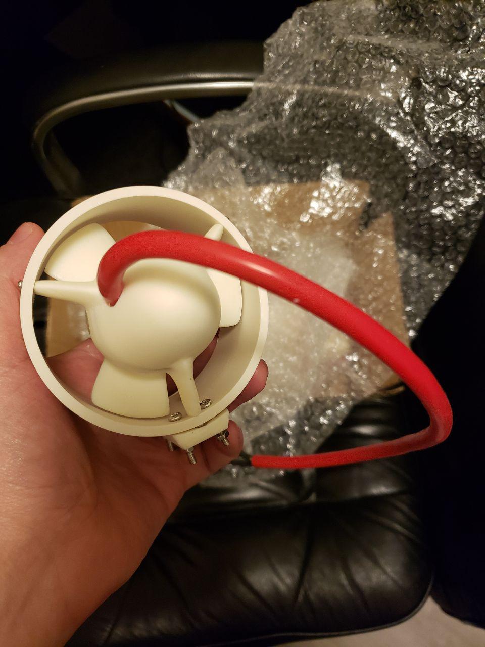
(Above) Big thrusters
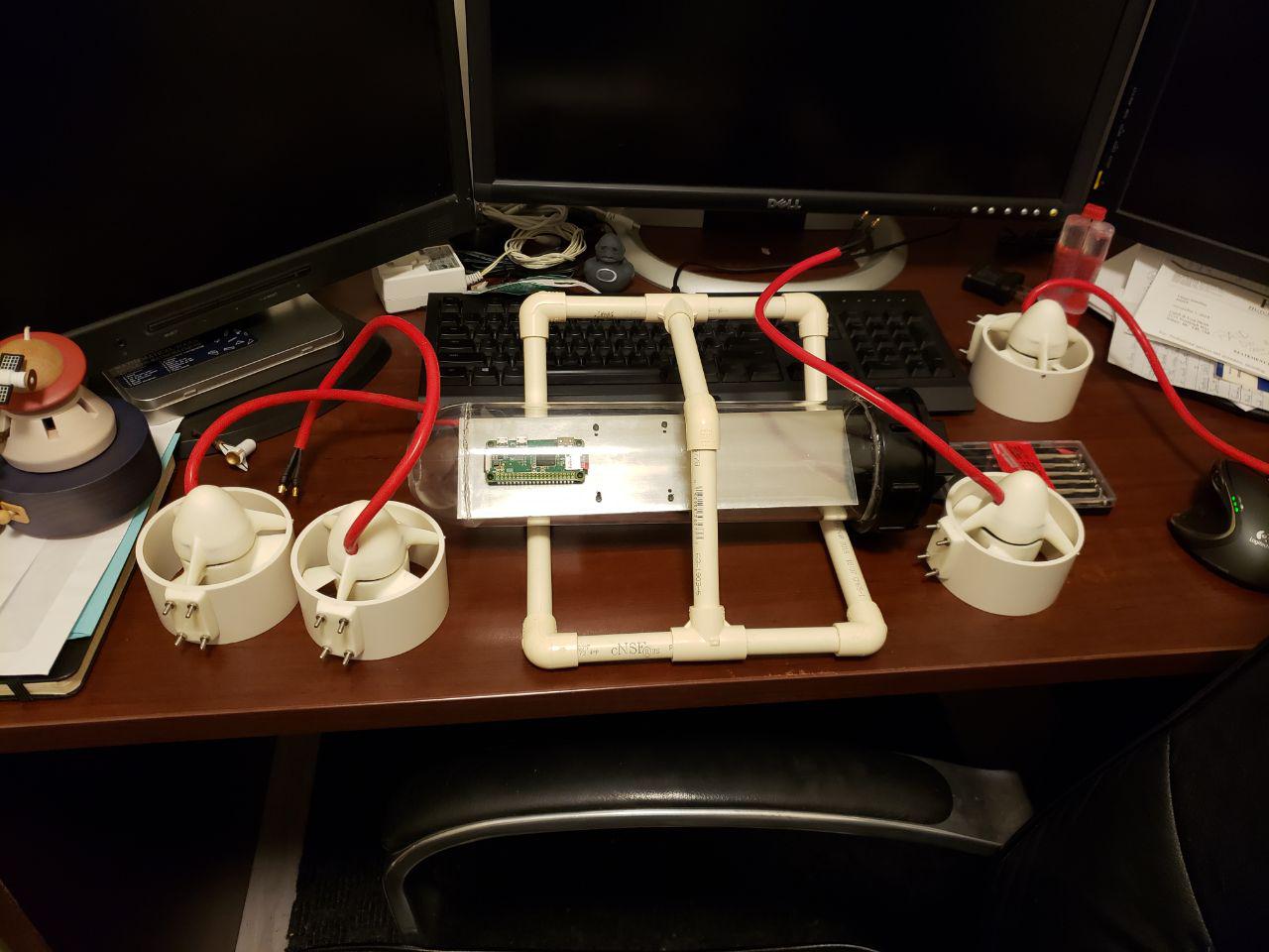
- The thrusters have arrived and I have started mounting them to the scaffolding. They will be mounted with the turn/forward/backward thrust on the sides (facing forward and back), and the other two thrusters will be used for upward and downward thrust. I have 2 options for that — front-back position, or mirrored side thrusters (facing up). If I go front-back, I also get tilt, but there isn’t much real-estate on the scaffolding for that. We will see.
- I have started writing the software for the ROV — there will be a basic server on the sub that the command station connects to. The command station software will take joystick commands and relay them to the sub via network connection. The video feed will come through on the same wire. This can be improved to be completely autonomous but that will be a future project.
- I am still waiting on the ESCs so I can’t test the entire thruster configuration just yet. Once those come in, I will be able to start testing the software on the physical platform with the actual hardware.
- I still need to do a full 30m pressure test on the chassis. I plan on doing another layer of epoxy over all areas that were cemented as these are the most obvious places of failure.
- I need to mount the camera at the front of the electronics plate — position is extremely important so this will take some precision.
- I am custom-manufacturing some water-proof LEDs for the ROV, and still waiting for the parts to be shipped to me. (Basic 1 inch PVC pipe, reflective light backing, and LEDs). I plan on making these fully self-contained and will mount to the scaffolding. Battery draw will be minimal.
I will post Part 2 of this project when the ROV is complete

You must be logged in to post a comment.